Material:
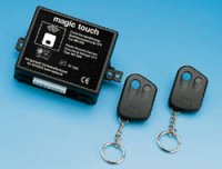
For this project, I used Waeco's radio Remote Control, the Magic Touch type "MT-350". Waeco is a so-called Original Equipment Manufacturer (OEM) and the kit can be bought from Conrad electronics for DM 199.
They can also supply less expensive versions. However the MT-350 offers the following interesting features:
- two remote senders
- remote senders are simply styled (no transparent "disco" plastic)
- includes interface to turn indicators
- compatible with the ML 22/44 central locking
- includes extra user-definable button
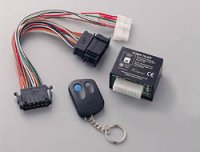
Components of the MT-350 Remote Control system:
The kit comprises:
- Controller
- 2 remote senders
- Set of cables for the quick, simple assembly
- Copy-safe control unit with 4.3 billion possible codes
- Good range (up to 20 meters)
- Expandable - up to 5 remote senders
- (German) post office approved with Europe-wide operating permit
- Fitting instructions
Terminology:
CL-Controller - Central Locking controller
RC-Controller - Remote Control controller
Basics:
The Radio Control inter-operates with the vehicle's central locking.
If you press the activation button on the remote sender, then the RC-controller sends a signal to the CL-controller. This open/closes the vehicle.
Additionally the RC-controller powers vehicle's turn indicators to display the open/closed status.
Possible additional functions:
- automatic relocking, if the door is not opened for 30 seconds after unlocking. (In addition the interior light must operate. I haven't implemented this (yet))
- interior light is only switched off when the ignition is switched on. (For this also, the interior light must operate. I haven't implemented this (yet))
- Auxiliary function (electric windows, or boot opener)

Installation:
I put the two controllers (RC and CL) low on the right in the foot well (near the fuse box). After connecting a 12 V operating voltage (both control units get a permanent supply from e.g. the radio), the two units are connected to each other (see connection diagram No. 8 of the user manual). Since I installed the central locking actuators in the reversed sense, the control cables had to be reversed; pin 11 of the RC-controller to pin 5 of the CL-controller and pin 14 to pin 10. In order to inhibit automatic relocking (which is is implemented by default) the RC controller's yellow control line must be connected to ground.

Interface to the Turn Indicators:
First I was not at all interested in implementing the interface to the turn indicators. But I quickly realised that this function is more than cosmetic. Without it, you can be never be too sure whether the RC has just opened or closed.
For the turn indicator interface, I simulated operation of the indicator stalk. More specifically, I tapped the wires of the logic elements to the wiring harness. This is best achieved by lowering the steering wheel on its vertical adjustment. Under the steering wheel hub you should now see the connecting plug. Loosen this plug, tap into the green/grey and green/yellow cables and connect to pins 7 and 8 of the RC-controller.
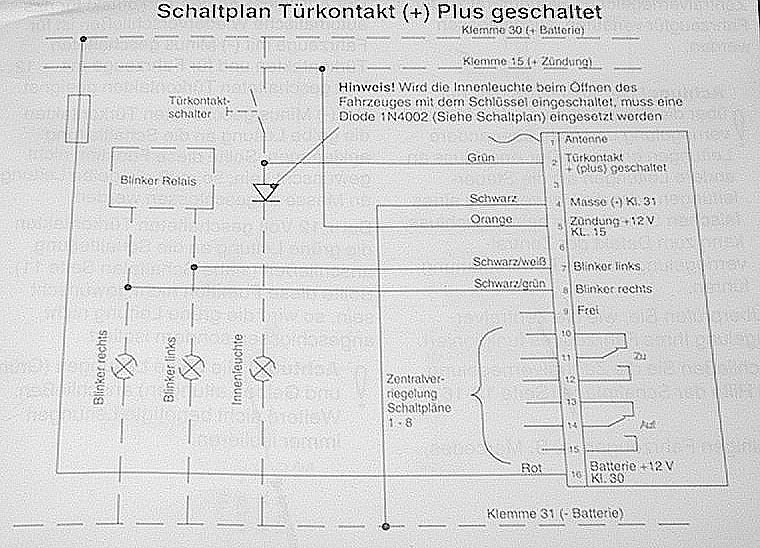
However, I don't think that this is the best method, since the control is exercised upstream of the flasher relay. I get shallow, uneven blinking. Mayb someone with better knowledge of the wiring loom and/or KFZ(?) electronics, could tell me where to tap the cables of the turn signal bulbs directly.
Test the locking. Does everything flash? Beautiful. Then put everything back together, tidy up the wiring with cable ties, clear away the tools, and open a bottle of beer. Then sing: OPEN - CLOSED - OPEN - CLOSED - OPEN - CLOSED - OPEN - CLOSED -OPEN - CLOSED .......
Have fun tinkering - Yours Ronald - 19 July 2001